
Stovepipes
Pipe Types
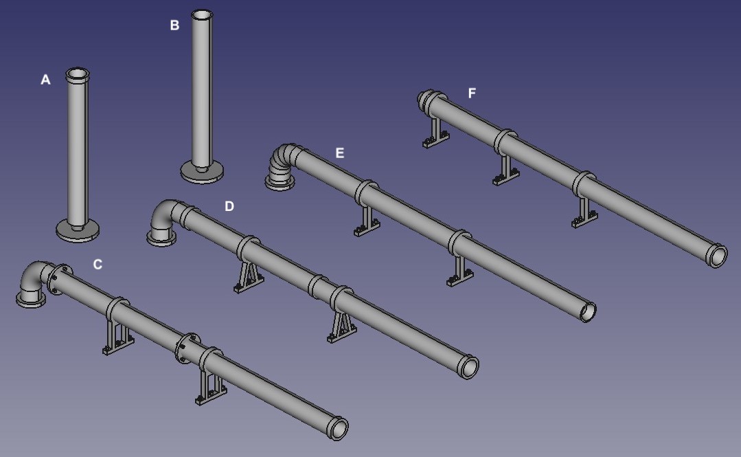
This page describes my current range of model stovepipes, by which I mean chimneys made of metal tubes. These are 3D-printed in UV resin, and are available in a selection of styles, shapes, sizes, and in a variety of scales. They are intended to be fitted to your model building, either protruding through its roof or attached to a wall. The smaller sizes may also be of use for model boats and caravans, and the larger sizes could also be used to represent ventilation pipes. The current range of basic stovepipe types is shown in the illustration below:
Stovepipe Types
Note: Clicking on any of the images on this page, such as that above, will cause a larger version of the image to appear in a new tab or window of your browser (depending on how your browser is set up).
The basic pipe types available are short, through-roof (A & B) or long, wall-mounted (C – F). The short types are printed vertically, and have a thin enlarged base for stability during printing, which will generally need to be cut off. To help with the cutting, the bottom of the pipe is tapered. Both types of pipe are available with a recessed upper end that matches this taper, so that several pipes can be joined together to make a longer one (B, E). Alternatively, the pipes can be supplied with a recessed end that models a real open-ended pipe, complete with a thicker rim (A, C, D, F). The recesses extend only a couple of mm into the pipe, for reasons of strength and printability.
The long, wall-mounted pipes can be supplied with a bend at the lower end, to take the pipe through the wall, a number of wall supports, and/or a number of simulated joints. The bends can be smooth (C & D) or segmented (E). The wall supports can be single-strut (E & F), triangle strut (B), or rectangle strut (C). The simulated joints can be socket (D), to model the case where a real pipe is plugged into the end socket of another, or bolted flange (C).
Crown Types
Cap Types
Cage Types
Cowl Types
Depending on the number of supports you specifiy, and their spacing, I may need to add additional temporary supports during printing. I will cut these off before dispatch, but you may need to tidy up the underside (facing the wall) of the pipe with a small file or abrasive paper.
All of the pipes shown in the illustrations use a pipe size 7.5 inches in diameter, 5 or 12 feet long, in 4 mm scale. The wall-mounted pipes are set about 1 ft from the wall (to the pipe centreline). These dimensions refer to the prototype size; the size of the model pipes will then depend on the scale chosen. Elsewhere on this page dimensions given in feet and/or inches likewise refer to the prototype size. (A table to help convert prototype inches into model mm is given at the bottom of this page.) Subsequent illustrations also use these pipe sizes as standard.
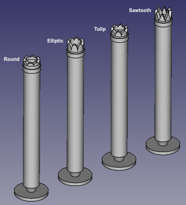
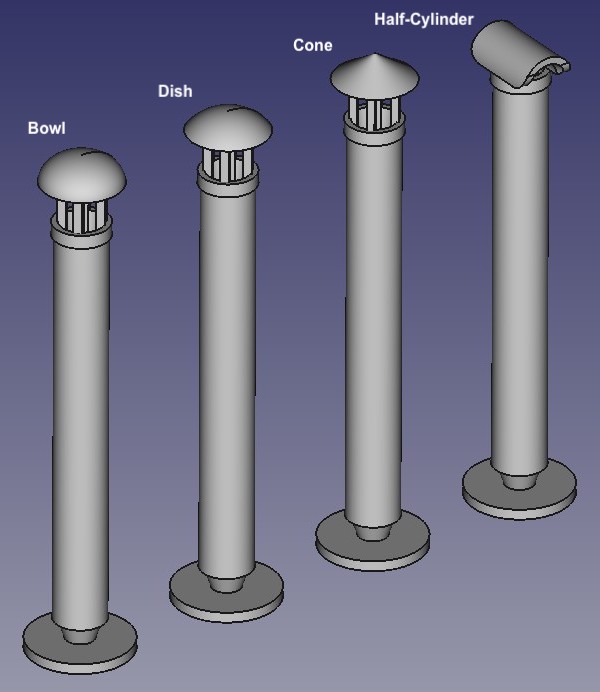
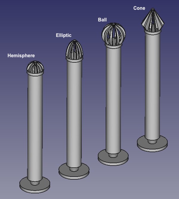
A variety of additional features can also be added to the top of the short pipe types, as illustrated in the images to the right. It is unfortunately not possible to include these features on the long pipe types, because they cannot be properly printed horizontally. To model a wall-mounted pipe with these features you will therefore have to join a short pipe with the required top to a long pipe. To help hide the join, it is best to arrange the lengths of the pipes so that the join occurs at (ideally just below) a support or simulated joint position in the long pipe. To help with this, a flange or socket joint can be added to the bottom of the short pipe. The top features currently available are:
Crowns
These consist of a number of "teeth" arranged around the rim of the pipe, giving the effect of a "crown" on top of the pipe. The tooth shapes available are:
- Triangular, giving a "sawtooth" effect.
- Circular with a pointed top, giving a "tulip" petal effect.
- Half-elliptical.
- Half-circular.
The number of teeth will depend on the diameter of the pipe chosen – the crowns shown have 8 teeth.
Caps
Four different caps can be added to a basic short pipe:
- Elliptical bowl, supported on top of the pipe by 4 legs. If configured with a cap height equal to its radius, the bowl becomes a hemisphere.
- Spherical dish cap, supported on top of the pipe by 4 legs.
- Conical cap, supported on top of the pipe by 4 legs.
- Half-cylinder resting on top of the pipe.
In each case, the end of the pipe is recessed, as described above for the open-ended basic pipe. As appropriate, the caps can be configured for cap diameter, cap height, and leg height. (The caps shown have a 2:1 ratio of diameter to height, and 6 in legs.) For the half-cylinder cap, the cylinder diameter is the same as the top of the pipe, and the length of the cylinder set to overhang the pot by 1.5 inches each side (i.e. the length is the pot (top) diameter plus 3 inches).
Cages
Four different cages can be added to a basic short pipe, to represent a real wire cage pipe top, although the strips making up the model cage are rather thicker than real wires for reasons of strength and printability, especially in the smaller scales:
- Hemisphere.
- Elliptic.
- Ball.
- Raised Cone.
The height and diameter of the cages is set according to the diameter of the pipe. The supporting pipe does not have the recessed top described above.
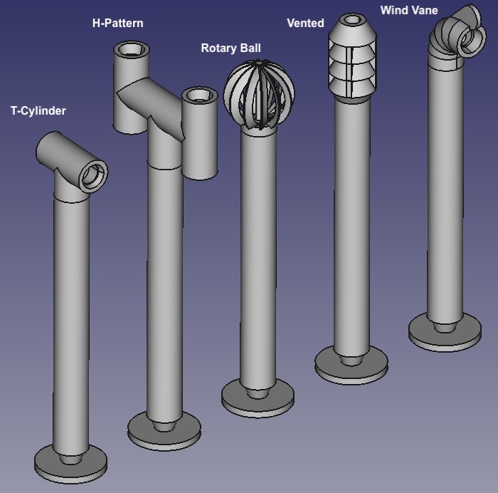
Cowls
The following different cowls are available:
- T-cylinder, resting on top of the pipe. The diameter of the cylinder is the same as pipe. Its length is 3 in longer than the diameter.
- H-pattern, consisting of interconnected tubes arranged in the shape of a letter "H" (plus the central leg). The tops of the end tubes are recessed in a similar manner to the basic pots. The diameter of all of the tubes is the same as the pipe. Configurable for tube lengths.
- Rotary ball.The prototype consists of a cage of multiple vanes that rotate in the wind. The model version does not rotate. The overall diameter of the ball is set to 1.5 x pipe diameter.
- Vented, consisting of multiple open-ended cones stacked on top of the pot. The number of cones is configurable; the cone diameter and height is set relative to the diameter of the pipe. The undersides of the cones are joined to the cone below without a gap (for ease of printing and strength), not open as in the prototype.
- Wind vane, consisting of a right-angled segmented tube on top of the pipe. In the prototype the tube rotates with the wind; the model version does not move. The tube diameter is equal to the diameter of the pipe, and the bend radius set accordingly. Only the end two segments are open.
The supporting pipe does not have the recessed tops described above.
Configure Your Pipes
To order some of my stovepipes you will need to configure each pipe specification and add the appropriate quantity to your basket. Select the basic pipe type (as described above). To add a crown, cap, cage or cowl, select the type you require and click on the "Change Type" button. Further controls will then appear that will allow you to set the various dimensions etc. of the cap etc. You will also then be able to set the quantity of pipes to include in your basket. Each pipe will cost £0.45.
To keep the number of configuration option values down, while still covering the wide range of scales, many of the configurable dimensions are specified in scale inches, rather than model mm. A calculator and look-up table to help convert scale inches into model dimensions (or vice versa) is available here (opens in new browser tab/window).
Note: If you want a stovepipe component that is not covered by the standard options below, I will be happy to quote you for a customised component. Please contact me with full details.