
External Pipes
These components are 3D-printed in UV resin, and are available in a selection of styles, shapes, sizes, and in a variety of scales. They are intended to be fitted to the walls of your model building, to represent various types of external pipes such as downpipes from gutters and roofs; soil pipes from internal toilets, sinks and baths; and other forms of external plumbing.
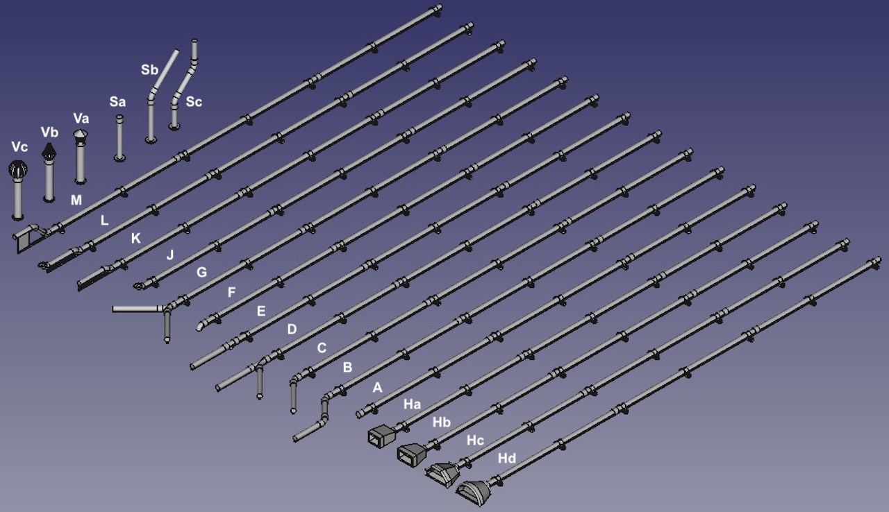
The current range of pipes is shown in the diagram below. The standard pipe components can be easily cut up and joined together to produce a wide variety of pipework for a model building. The long pipes (A–M and Ha–d) include moulded representations of wall attachment brackets (at approx scale 4ft intervals) and pipe connections. I recommend that, whenever possible, pipes be cut and joined togther immediately to one side of a bracket or connection, to make the joint less obvious. The smaller pipe diameters can be easily cut using a sharp knife or sprue cutters; larger diameter may be best cut using a fine-toothed razor saw. In both cases, before joining you will need to tidy up and make square the cut ends on each side of the joint to make sure they fit together as well as possible.
Pipe Types
Note: Clicking on any of the images on this page, such as the one above, will cause a larger version of the image to appear in a new tab or window of your browser (depending on how your browser is set up).
The long pipes also incorporate a narrow support strip between the pipe and wall. This is to help with the printing process. For the smaller pipe sizes and scales this strip is best left in place: it will be difficult to see in the finished model, unless you deliberately look closely along the wall of your building. For larger pipes and scales the strip may be more visible, so you may prefer to carefully reduce or remove the strip between the mounting brackets. I generally recommend painting the strip the same colour as the rest of the pipe, at least for darker pipe colours. For lighter colours you might like to try painting the strips a darker colour (to simulate the shadow?), or even the wall colour. The pipes are best painted before attaching them to your building.
Many buildings have walls that thicken for a few brick courses at the bottom, or have a variable wall thickness to give a decorative "panelling" effect. Pipes K and L allow a pipe run to negotiate such steps in wall thickness. Alternatively, you could use pipes with a larger wall offset along their entire length, then reduce or cut away the support strip under the pipe where the wall thickens.
Key Pipe Dimensions
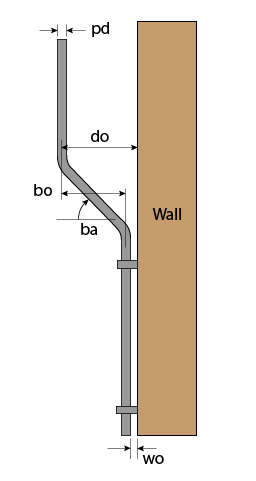
To accommodate a range of prototypes, the various pipe types are configurable for various key dimensions, as shown in the diagram opposite:
pd – pipe diameter. For square pipes, the "diameter" is the distance between opposite faces.
wo – wall offset, the distance of the edge of the pipe from the wall.
do – downpipe offset, the distance from the centre of the gutter downpipe junction to the wall.
bo – bend offset, the distance between centres of the pipe on either side of double bend or step.
ba – bend or branch angle, the angle between the sloping part of the pipe and horizontal.
The pipes are available with a round or square profile, and in a range of diameters to match my range of gutter components, plus selected larger sizes to represent soil pipes etc. The pipe size (diameter) required to match a gutter size is shown in the table below. The last two rows do not correspond to a gutter shape, but are there to represent larger pipes, such as soil pipes. The pipe sizes of Mini, Std, XL, XXL, and XXXL approximately correspond to prototype diameters of 2, 3, 4, 5, and 6 inches, respectively.
| Gutter Shape | Pipe Size | Scale | |||||||||
|---|---|---|---|---|---|---|---|---|---|---|---|
| 2 mm | 1:120 | 3 mm | 3.5 mm | 4 mm | 7 mm | 1:32 | 10 mm | 1:22.5 | 16 mm | ||
| Round Mini | Mini | 0.5 | 0.55 | 0.6 | 0.7 | 0.75 | 1.3 | 1.8 | 1.9 | 2.6 | 3.0 |
| Round Std | Std | 0.6 | 0.7 | 0.8 | 0.9 | 1.0 | 1.75 | 2.4 | 2.5 | 3.4 | 4.0 |
| Round Deep | Std | 0.6 | 0.7 | 0.8 | 0.9 | 1.0 | 1.75 | 2.4 | 2.5 | 3.4 | 4.0 |
| Round XL | XL | 0.8 | 0.9 | 1.0 | 1.2 | 1.4 | 2.4 | 3.3 | 3.5 | 4.7 | 5.6 |
| Square | Std | 0.6 | 0.7 | 0.8 | 0.9 | 1.0 | 1.75 | 2.4 | 2.5 | 3.4 | 4.0 |
| Offset | XL | 0.8 | 0.9 | 1.0 | 1.2 | 1.4 | 2.4 | 3.3 | 3.5 | 4.7 | 5.6 |
| - | XXL | 0.9 | 1.1 | 1.3 | 1.5 | 1.7 | 2.9 | 4.0 | 4.2 | 5.7 | 6.7 |
| - | XXXL | 1.0 | 1.25 | 1.5 | 1.8 | 2.0 | 3.5 | 4.8 | 5.0 | 6.8 | 8.0 |
Scales are mm:1ft, all dimensions in mm.
Pipe Types
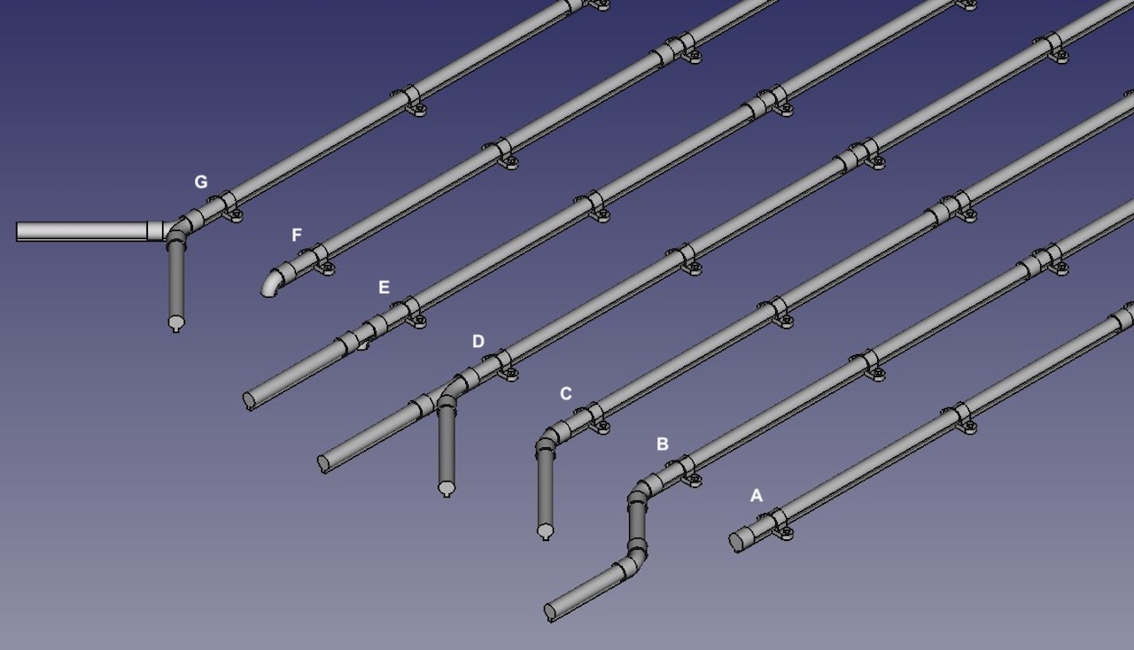
Closeup, Pipes A–G
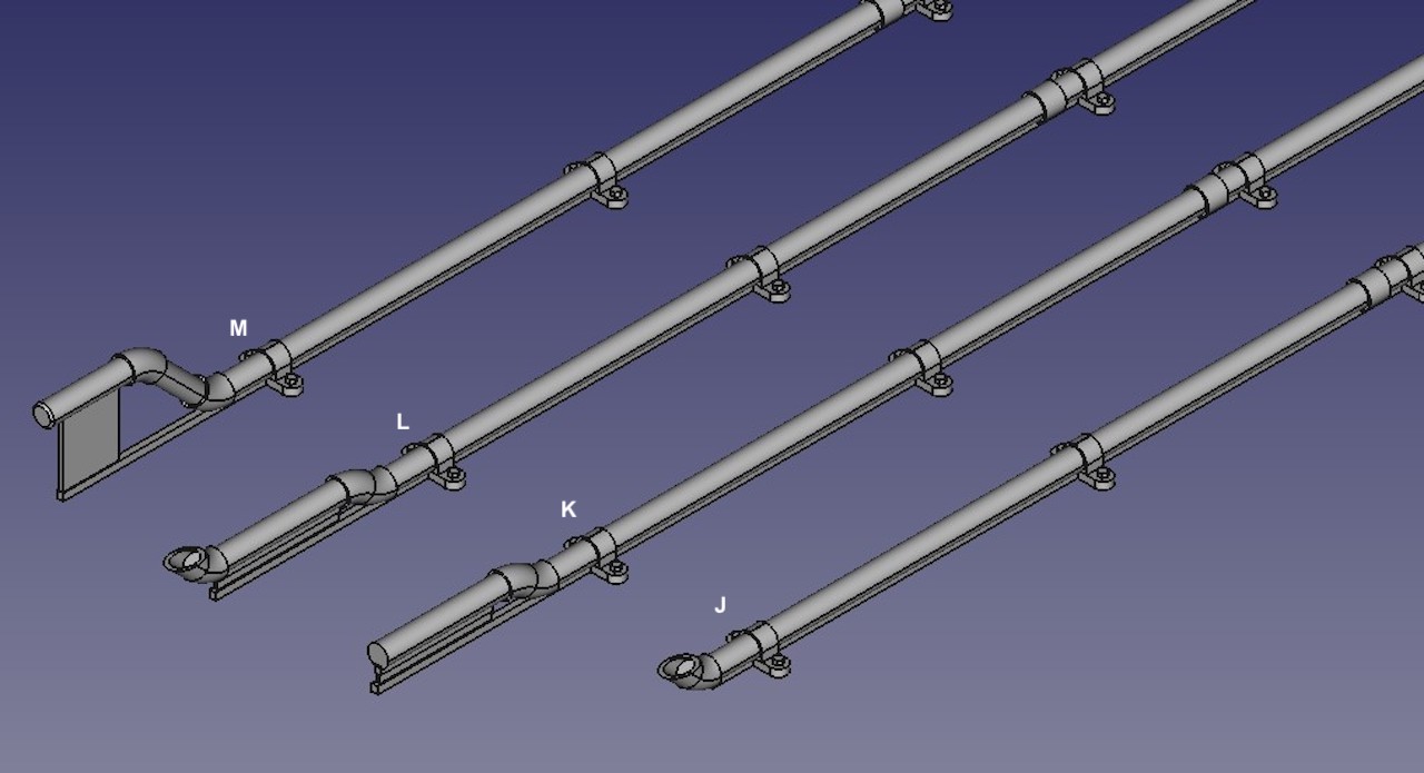
Closeup, Pipes J–M
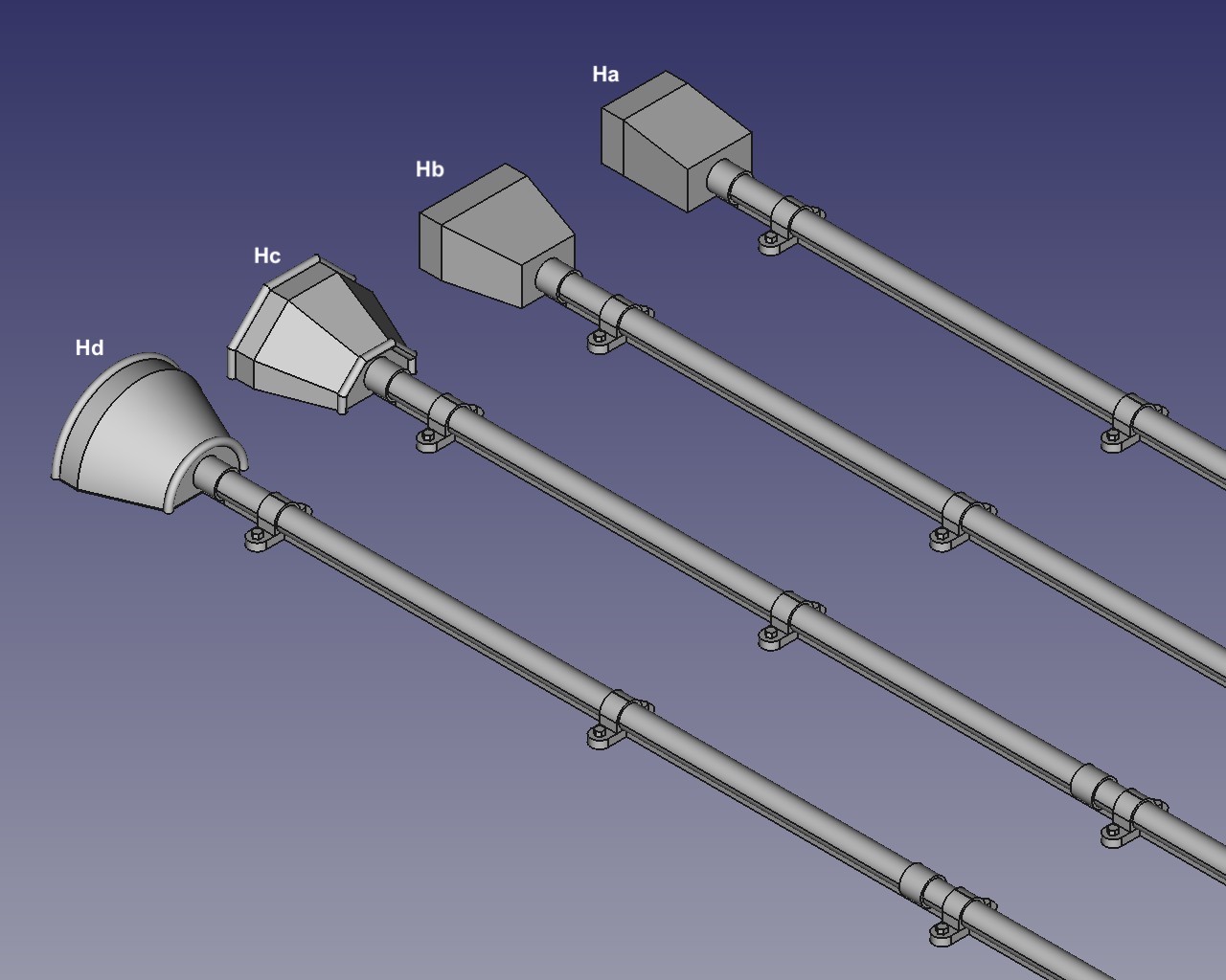
Closeup, Hopper Pipes Ha–Hd
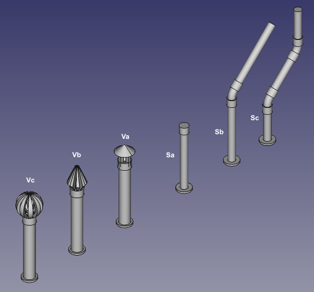
Closeup, Short Pipes Sa–Sc and Va–Vc
The pipe types available, as illustrated above and opposite (for a 1 mm round pipe shape in 4mm scale), are:
Long Pipes
- A: Plain pipe,
- B: Pipe with double or offset bend parallel to the wall,
- C: Pipe with single bend parallel to the wall,
- D: Pipe with side branch,
- E: Pipe with into-wall branch,
- F: Pipe with into-wall bend,
- G: Pipe with symmetrical "Y" side branches,
- J: Pipe with end spout,
- K: Pipe with small step perpendicular to wall,
- L: Pipe with small step and end spout,
- M: Pipe with large perpendicular step, for mating with gutter,
Pipes B–D are available in left- and right-hand versions (the bend or branch is to the left or right of the pipe, as viewed when fitted to the building).
The main length of the pipes are 100 mm long plus the special ends.
For pipes B–E and G the lengths of the special ends are configurable, but of limited length. Longer runs can be acheived by replacing the short ends with lengths of plain pipe (or offcuts from other pipe types), which can include attachment brackets etc.
Pipes K–M have vertical steps that require extra support during printing. These supports are easily removed prior to installation on your model.
Hopper Pipes
These are simiar to the long pipes, but have a hopper or water collector at the end. These are used to collect water from flat roofs, or other roofs with a parapet, valley gutters between adjacent roofs, or can be fed by multiple pipes to act as a junction in place of branched pipes. Four styles of hopper are available:
- Ha: Rectangular hopper with single taper,
- Hb: Rectangular hopper with double taper,
- Hc: Ogee (half-octagon) hopper,
- Hd: Round (semi-circle) hopper,
The hoppers have shallow recessed tops, to give an impression of the open top of the prototype. The pipes are 100 mm long, plus the height of the hopper. The Round and Ogee hoppers have decorative ridges around the top and bottom rims.
The hoppers are configurable in size using the dimensions in the diagram below.
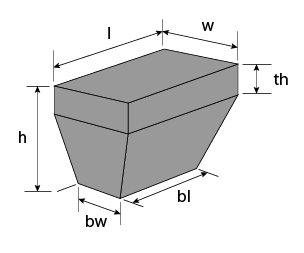
Hopper Dimensions
- h: height of hopper body,
- l: length of hopper body (at top),
- w: width of hopper body (at top),
- bl: length of hopper body at bottom,
- bw: width of hopper body at bottom,
- th: height of non-tapered section.
Short Pipes
These are printed vertically rather than horizontally, so don't have the narrow strip under the pipe. They also don't have moulded support brackets. They are, however, of limited length because of the vertical printing and depending on pipe diameter may have a thin enlarged base that helps with the printing process and will generally need to be removed during installation on your model. The following styles are available:
- Sa: Plain pipe, with end coupler,
- Sb: Pipe with single bend,
- Sc: Pipe with double or offset bend,
- Va: Plain pipe with conical end cap attached to the pipe with 4 legs,
- Vb: Plain pipe with conical cage vent,
- Vc: Plain pipe with ball cage vent,
Pipes Sb and Sc could help modelling a gutter downpipe that runs down the end wall of a building rather than the more usual side wall that is parallel to the gutter (as provided for by pipe type M). The short pipe can be joined to the gutter junction and an appropriate shape of long pipe (A–G) fixed to the end wall. Pipe Sc could also be of use for a side downpipe with an offset section that is not perpendicular to the wall.
Pipes Va–c are intended to model the vents at the end of a soil pipe. Vents for internal soil pipes can be modelled by inserting the vent pipe vertically into a hole in the roof, rather than joining it to an external pipe. They could also be used to model a short stovepipe. The end cap and cages are configurable for size.
Configure Your Pipes
To order some of my pipe components you will need to configure each pipe specification and add the appropriate quantity to your basket. First select the basic pipe type (as described above) and click on the "Select" button. Further controls will then appear that will allow you to set the various dimensions etc. of the pipe and set the quantity of the pipe to include in your basket. Each pipe component will cost £0.95.
To keep the number of configuration option values down, while still covering the wide range of scales, many of the configurable dimensions are specified in scale inches, rather than model mm. A calculator and look-up table to help convert scale inches into model dimensions (or vice versa) is available here (opens in new browser tab/window).
Note: If you want a pipe component that is not covered by the standard options below, I will be happy to quote you for a customised components. Please contact me with full details.